1. Relational Database Systems
The component of Microsoft SQL Server called the Database Engine is a relational database system. In contrast to earlier database systems (network and hierarchical), relational database systems are based upon the relational data model, which has a strong mathematical background.
The central concept of the relational data model is a relation—that is, a table. Therefore, from the user’s point of view, a relational database contains tables and nothing but tables. In a table, there are one or more columns and zero or more rows. At every row and column position in a table there is always exactly one data value.
1.1. Working with the Book’s sample Database
The sample database used in this book represents a company with departments and employees. Each employee in the example belongs to exactly one department, and each department has one or more employees. Jobs of employees center on projects: each employee works at the same time on one or more projects, and each project engages one or more employees.
The data of the sample database can be represented using four tables:
- department
- employee
- project
- works_on
Tables 1-1 through 1-4 show all the tables of the sample database.
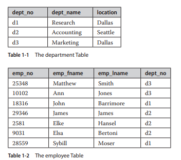

The department table represents all departments of the company. Each department has the following attributes:
department (dept_no, dept_name, location)
dept_no represents the unique number of each department, dept_name is the name of each department, and location is the location of the corresponding department.
The employee table represents all employees working for the company. Each employee has the following attributes:
employee (emp_no, emp_fname, emp_lname, dept_no)
emp_no represents the unique number of each employee. emp_fname and emp_lname are the first name and last name of each employee, respectively. Finally, dept_no is the number of the department to which the employee belongs.
Each project of the company is represented in the project table. This table has the following columns:
project (project_no, project_name, budget)
project_no represents the unique number of each project. project_name and budget specify the name and the budget of each project, respectively.
The works_on table specifies the relationship between employees and projects. It has the following columns:
works_on (emp_no, project_no, job, enter_date)
emp_no specifies the employee number and project_no specifies the number of the project on which the employee works. The combination of data values belonging to these two columns is always unique. job and enter_date specify the task and the starting date of an employee in the corresponding project, respectively.
Using the sample database, it is possible to describe some general properties of relational database systems:
- Rows in a table do not have any particular order.
- Columns in a table do not have any particular order.
- Every column must have a unique name within a table. On the other hand, columns from different tables may have the same name. (For example, the sample database has a dept_no column in the department table and a column with the same name in the employee table )
- Every single data item in the table must be single valued. This means that in every row and column position of a table there is never a set of multiple data values.
- For every table, there is usually one column with the property that no two rows have the same combination of data values for all table columns. In the relational data model, such an identifier is called a candidate key. If there is more than one candidate key within a table, the database designer designates one of them as the primary key of the table. For example, the column dept_no is the primary key of the department table; the columns emp_no and project_no are the primary keys of the tables employee and project, respectively. Finally, the primary key for the works_on table is the combination of the columns emp_no and project_no.
- In a table, there are never two identical rows. (This property is only theoretical; the Database Engine and all other relational database systems generally allow the existence of identical rows within a table.)
1.2. SQL: A Relational Database Language
The SQL Server relational database language is called Transact-SQL (T-SQL). It is a dialect of the most important database language today: Structured Query Language (SQL). In contrast to traditional languages like C, C++, and Java, SQL is a set-oriented language. (The former are also called record-oriented languages.) This means that SQL can query many rows from one or more tables using just one statement. This feature is one of the most important advantages of SQL, allowing the use of this language at a logically higher level than the level at which traditional languages can be used.
Another important property of SQL is its nonprocedurality. Every program written in a procedural language (C, C++, Java) describes how a task is accomplished, step by step. In contrast to this, SQL, as any other nonprocedural language, describes what it is that the user wants. Thus, the system is responsible for finding the appropriate way to solve users’ requests.
SQL contains two sublanguages: a data definition language (DDL) and a data manipulation language (DML). DDL statements are used to describe the schema of database tables. The DDL contains three generic SQL statements: CREATE object, ALTER object, and DROP object. These statements create, alter, and remove database objects, such as databases, tables, columns, and indexes. (These statements are discussed in detail in Chapter 5.)
In contrast to the DDL, the DML encompasses all operations that manipulate the data. There are always four generic operations for manipulating the database: retrieval, insertion, deletion, and modification. The retrieval statement SELECT is described in Chapter 6, while the INSERT, DELETE, and UPDATE statements are discussed in detail in Chapter 7.
2. Database Design
Designing a database is a very important phase in the database life cycle, which precedes all other phases except the requirements collection and the analysis. If the database design is created merely intuitively and without any plan, the resulting database will most likely not meet the user requirements concerning performance. Another consequence of a bad database design is superfluous data redundancy, which in itself has two disadvantages: the existence of data anomalies and the use of an unnecessary amount of disk space.
Normalization of data is a process during which the existing tables of a database are tested to find certain dependencies between the columns of a table. If such dependencies exist, the table is restructured into multiple (usually two) tables, which eliminates any column dependencies. If one of these generated tables still contains data dependencies, the process of normalization must be repeated until all dependencies are resolved.
The process of eliminating data redundancy in a table is based upon the theory of functional dependencies. Afunctional dependency means that by using the known value of one column, the corresponding value of another column can always be uniquely determined.
(The same is true for column groups.) The functional dependencies between columns A and B is denoted by A ^ B, specifying that a value of column A can always be used to determine the corresponding value of column B. (“B is functionally dependent on A.”)
Example 1.1 shows the functional dependency between two attributes of the table employee in the sample database.
![]()
By having a unique value for the employee number, the corresponding last name of the employee (and all other corresponding attributes) can be determined. This kind of functional dependency, where a column is dependent upon the primary key of a table, is called trivial functional dependency.
2.1. Normal Forms
Normal forms are used for the process of normalization of data and therefore for the database design. In theory, there are at least five different normal forms, of which the first three are the most important for practical use. The third normal form for a table can be achieved by testing the first and second normal forms at the intermediate states, and as such, the goal of good database design can usually be fulfilled if all tables of a database are in the third normal form.
2.2. First Normal Form
First normal form (1NF) means that a table has no multivalued attributes or composite attributes. (A composite attribute contains other attributes and can therefore be divided into smaller parts.) All relational tables are by definition in 1NF, because the value of any column in a row must be atomic—that is, single valued.
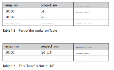
Table 1-5 demonstrates 1NF using part of the works_on table from the sample database. The rows of the works_on table could be grouped together, using the employee number.
The resulting Table 1-6 is not in 1NF because the column project_no contains a set of values (p1, p3).
2.3. Second Normal Form
A table is in second normal form (2NF) if it is in 1NF and there is no nonkey column dependent on a partial primary key of that table. This means if (A,B) is a combination of two table columns building the key, then there is no column of the table depending either on only A or only B.
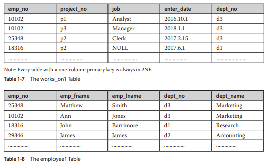
For example, Table 1-7 shows the works_on1 table, which is identical to the works_on table except for the additional column, dept_no. The primary key of this table is the combination of columns emp_no and project_no. The column dept_no is dependent on the partial key emp_no (and is independent of project_no), so this table is not in 2NF. (The original table, works_on, is in 2NF.)
2.4. Third Normal Form
A table is in third normal form (3NF) if it is in 2NF and there are no functional dependencies between nonkey columns. For example, the employeel table (see Table 1-8), which is identical to the employee table except for the additional column, dept_name, is not in 3NF, because for every known value of the column dept_no the corresponding value of the column dept_name can be uniquely determined. (The original table, employee, as well as all other tables of the sample database are in 3NF.)
2.5. Entity-Relationship Model
The data in a database could easily be designed using only one table that contains all data.
The main disadvantage of such a database design is its high redundancy of data. For example, if your database contains data concerning employees and their projects (assuming each employee works at the same time on one or more projects, and each project engages one or more employees), the data stored in a single table contains many columns and rows. The main disadvantage of such a table is that data is difficult to keep consistent because of its redundancy.
The entity-relationship (ER) model is used to design relational databases by removing all existing redundancy in the data. The basic object of the ER model is an entity—that is, a real- world object. Each entity has several attributes, which are properties of the entity and therefore describe it. Based on its type, an attribute can be
- Atomic (or single valued) An atomic attribute is always represented by a single value for a particular entity. For example, a person’s marital status is always an atomic attribute. Most attributes are atomic attributes.
- Multivalued A multivalued attribute may have one or more values for a particular entity. For example, Location as the attribute of an entity called ENTERPRISE is multivalued, because each enterprise can have one or more locations.
- Composite Composite attributes are not atomic because they are assembled using some other atomic attributes. A typical example of a composite attribute is a person’s address, which is composed of atomic attributes, such as City, Zip, and Street.
The entity PERSON in Example 1.2 has several atomic attributes, one composite attribute, Address, and a multivalued attribute, College_degree.
Example 1.2
PERSON (Personal_no, F_name, L_name, Address (City,Zip,Street),{College_degree})
Each entity has one or more key attributes that are attributes (or a combination of two or more attributes) whose values are unique for each particular entity. In Example 1.2, the attribute Personal_no is the key attribute of the entity PERSON.
Besides entity and attribute, relationship is another basic concept of the ER model.
A relationship exists when an entity refers to one or more other entities. The number of participating entities defines the degree of a relationship. For example, the relationship works_on between entities EMPLOYEE and PROJECT has degree two.
Every existing relationship between two entities must be one of the following three types:
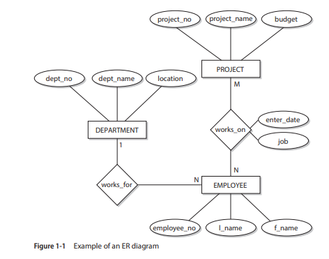
1:1, 1:N, or M:N. (This property of a relationship is also called cardinality ratio.) For example, the relationship between the entities DEPARTMENT and EMPLOYEE is 1:N, because each employee belongs to exactly one department, which itself has one or more employees. Also, the relationship between the entities PROJECT and EMPLOYEE is M:N, because each project engages one or more employees and each employee works at the same time on one or more projects.
A relationship can also have its own attributes. Figure 1-1 shows an example of an ER diagram. (The ER diagram is the graphical notation used to describe the ER model.) Using this notation, entities are modeled using rectangular boxes, with the entity name written inside the box. Attributes are shown in ovals, and each attribute is attached to a particular entity (or relationship) using a straight line. Finally, relationships are modeled using diamonds, and entities participating in the relationship are attached to it using straight lines. The cardinality ratio of each entity is written on the corresponding line.
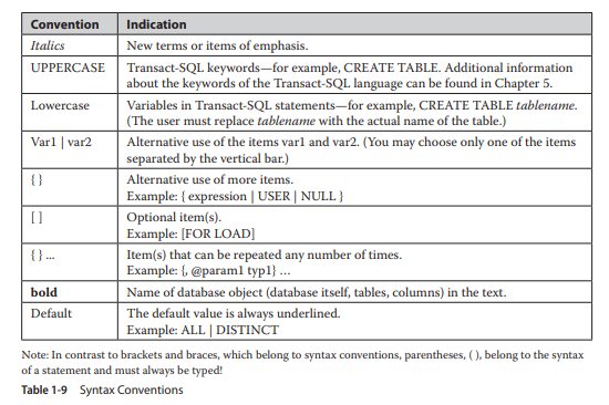
3. Syntax Conventions
This book uses the conventions shown in Table 1-9 for the syntax of the Transact-SQL statements and for the indication of the text.
Source: Petkovic Dusan (2020), Microsoft SQL Server 2019: A Beginner’s Guide, Seventh Edition-McGraw-Hill Education.